Building a Keyboard From Scratch
This article was typed using the finished keyboard.
Mechanical keyboards are all the rage today. Having a solid typing experience has never been as important to me as I have realized now. Often we are left to our squishy laptop keyboards, and they do get the job done. However, recently I have started to realize that a good keyboard is comparable to a good set of tires for a car, or good running shoes. This is the peripheral we interface the most as humans. Doesn't it make sense for this interface to not just be usable, but also pleasant and ergonomic?
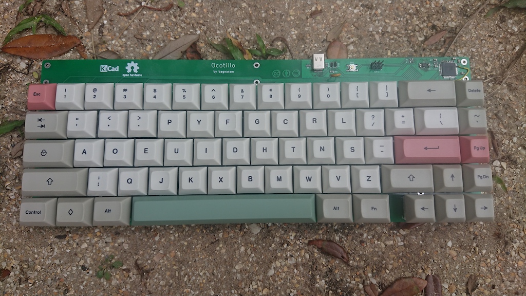
This is where we begin an overview of my keyboard project called "Ocotillo". This idea to build a fully-custom keyboard would re-invigorate my electrical engineering skills and prove to be quite a therapeutic experience during the quarantine. I started collecting research in the summer of 2020 and I made a few early decisions:
- I would be using KiCad for the schematic capture, and PCB design.
- The keyboard would have custom mechanical switches.
- It would natively support the DVORAK key layout
Schematic
The journey begins with the design of the schematic. I stumbled across the ai03 PCB Designer, which is a very thorough introduction to designing mechanical keyboards using KiCad. This guide goes through all the nuts and bolts of setting up a simple 4x4 key matrix from schematic to PCB. Do take a look at this.
I ended up designing project this around the AVR architecture. Previously built by Atmel before being acquired by Microchip, AVR has been a staple in my educational lab experience. The Atmega32u4 provides plenty of I/O for a 60% key design. (I had earlier wanted 75% but this was complicated by incorrectly purchasing the wrong keycap set from KBDFans). I centered around this architecture and iterated a few times until I determined I would build a 60% keyboard with USB-C interface and a dedicated ISP programming interface. This is a simple schematic and is further simplified by the examples given in the datasheet.
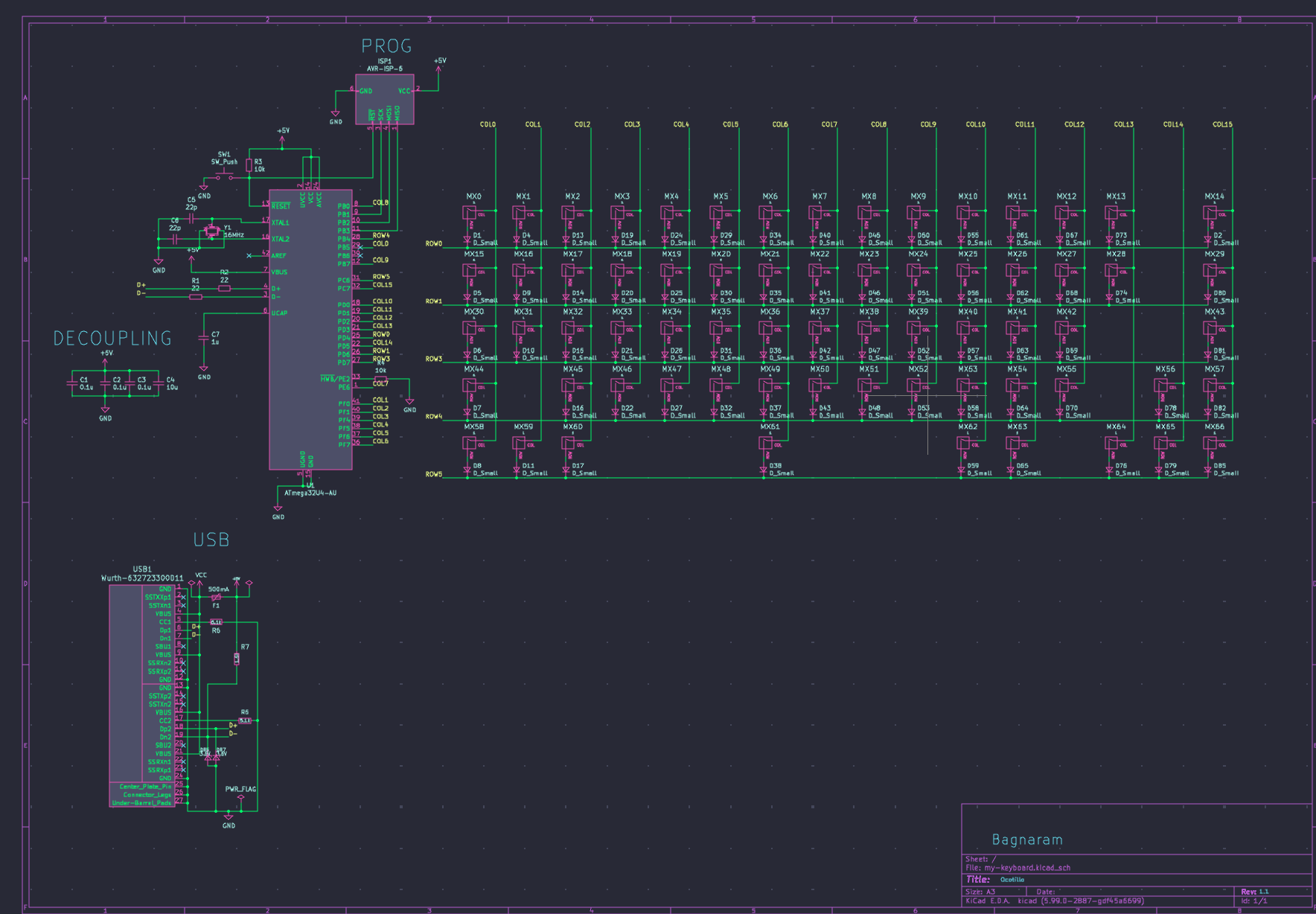
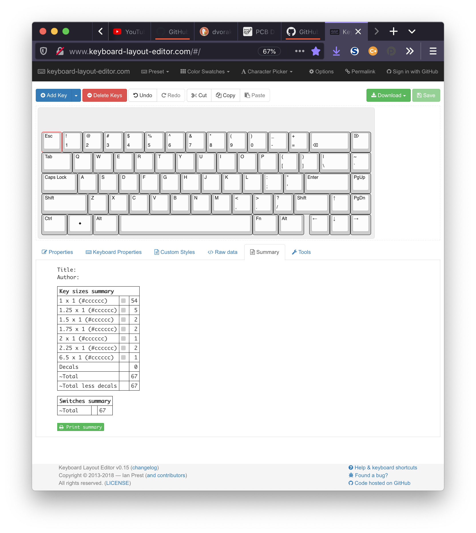
After completing the schematic, it was time to decide on a few things. I was not fully familiar with keyboard switch sizes and how they would be placed in the completed product and if everything would fit. After researching a bit, I decided to purchase the keycaps and switches next. This would prove useful later, when I construct the PCB. I would physically lay out the keyboard to determine a sizing that would fit, along with the help of the online Keyboard Layout Editor
By printing out PCB designs one-to-one on paper, I could lay out components on the paper and see if measurements are correct.
PCB Design
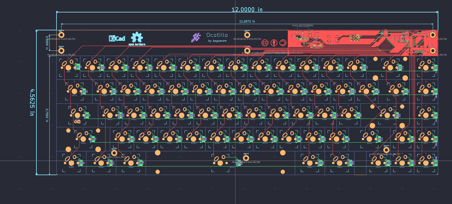
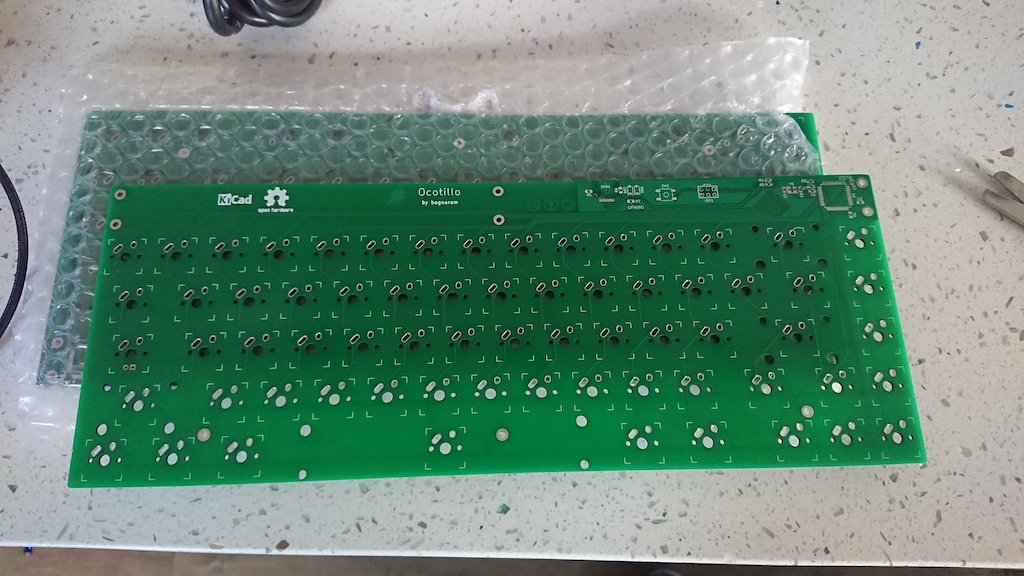
Taking the schematic over to PCB ended up being the most laborious exercise. I ended up going through several iterations of this project. Ai03's guide was another reference point. He also includes a set of KiCad custom libraries for MX style switches which proved to be very useful. I also looked at other open-source keyboard projects such as https://github.com/coseyfannitutti/discipline. I wanted to make sure everything would be exactly right at this point. Once you send the PCB Gerber files over to be fabricated, that's it so they better be right.
Laying out the traces, vias, and components can be considered an art, however quite mundane also. I had previously used Eagle PCB and before that [PCB Artist](https://www.4pcb.com/free-pcb-design-software.html). I had tried KiCad early on and found it to be quite lacking in features and quite buggy. That has all changed. After learning its shortcuts and also its library system, it has proved to be a very worthwhile open-source tool. I ended up laying out the PCB with ai03's MX library, and sourcing some of the other component libraries directly from Mouser. Once I felt everything was ready, I exported Gerber files and uploaded to JLCPCB.
Assembly
Constructing the final product required me to assemble a BOM from all my footprints. I decided to use the Mouser BOM tool because between them and DigiKey, Mouser carried all my components. I ordered all passive components, sockets, and the microcontroller from Mouser.
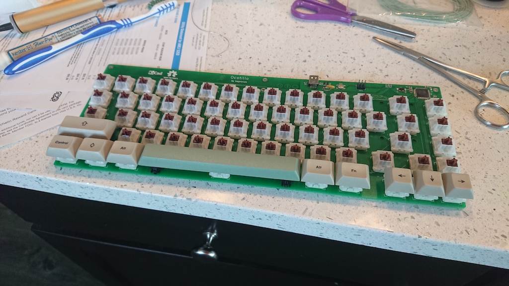
My keycaps were purchased from KBDFans and I was happy to find uniform-profile DSA keys in this attractive style. Uniform-profile keycaps are necessary when using non-standard key layouts like DVORAK because you can place them anywhere.
When the PCBs arrived, all components, mx switches, and stabilizers it was finally time for the moment of truth to see if everything physically fit. It did! So it was now time for the laborious yet somehow therapeutic process of soldering all SMD parts, switches, and TQFP microcontroller with just a conical soldering iron. At this point, having a flux pen is a must! Flux up the pads and let the solder flow. For small SMD components, I used the "tack-and-set" method where you tack one end of the component with solder to the board to keep it put. Then, flow the other end while the first end while still warm and it will "slide" into place.
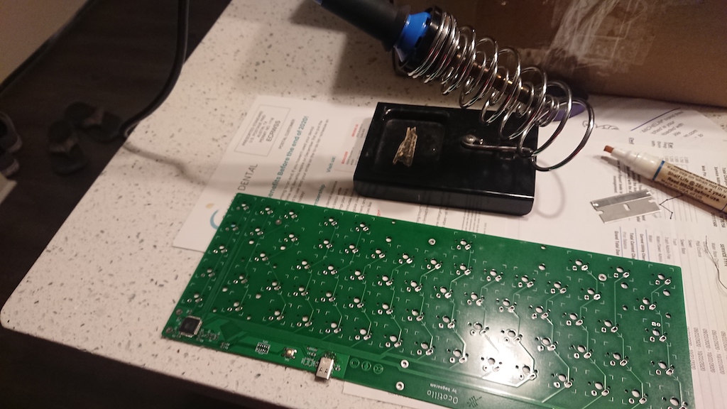
The TQFP was based on the Flux Glide method. The most incredibly difficult part was soldering the USB-C plug with its tiny pitch leads and through-hole leads. After 3 or so attempts of failed bridging leads, I finally got some clean solder joints. I don't suggest doing this by hand without flux, and a solder sucking tool!
Programming
The firmware for this project is based on the QMK Firmware project which offers an extensible framework for AVR-based keyboards. Because I provided this board with a dedicated ISP programming interface, I will be able to use my AVR-ISP mkII programmer to flash the device directly.
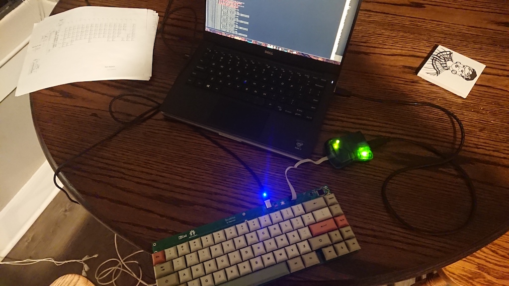
The QMK firmware setup is very simple. I was able to set up my keyboard mapping over a single evening.
The process is as follows:
Assign the keyboard rows and columns to the GPIO pins assigned to the microcontroller.
config.h
| |
Define the key matrix in code.
ocotillo.h
| |
Create DVORAK keymap.
keymaps/dvorak/keymap.c
| |
Assign the keymap to the default keyboard layout. (This is done by default since there is only one keymap defined.)
With the code built it is now time to compile with avr-gcc and flash it with AVRDude. To compile simply run the QMK makefile and then flash.
| |
Trial and Error
When flashing the board and powering the keyboard, I hooked it up and … nothing. Something must be wrong. The ISP programming interface worked so I knew the chip was healthy. After some tedious troubleshooting with my digital multimeter, I found that my USB D+ and D- pins were open.(one of them was shorted to ground it that pesky USB connector) I re-soldered the data pins and also found a misaligned GPIO pin(incorrectly assigned to AREF) in the microcontroller. I tacked a jumper wire to that and my RC oscillator on the MCU finally worked! After messing with the fuse settings in the AVR Fuse Calculator I found the proper configuration for my 16MHz clock crystal. With that, the device plugged into my PC and it finally was detected as an input device! It works!
Success
All in all, I would say this first revision was a success. Yes, there was some bodging done, but it still looks clean and I am happy with the final product. It is great to finally have a native DVORAK keyboard I can use to become more proficient. I have open-sourced this entire project, so take a look! I hope others can get as much out of this hobbyist project that I have been able to!
https://github.com/bagnaram/my-keyboard
https://github.com/bagnaram/qmk_firmware/tree/feature/ocotillo